Cause and Effect
Fixed Pitch Models
How Blade Fixed Pitch Models Fly
The goal in this tutorial is to provide a beginner with a baseline of knowledge about how helicopters fly in general and the differences between the fixed pitched Blade models, collective pitch models and full-size collective pitch helicopters. There is much more more happening than meets the eye when a pilot moves the cyclic and the helicopter moves out of hover in the directional flight and understanding the cause and effect of how a helicopter flies is like putting together a picture puzzle: there are a lot of different pieces and they don't provide a clear picture of what is happening on a cause and effect level until all the pieces are fit together correctly.
Lift
The first concept to understand is aerodynamic lift. Lift is defined as force that is perpendicular to the direction of air passing over an airfoil. The net effect of the shape of the airfoil and it angle to the air passing over it is a differential in air pressure which causes the airfoil to move up or down.
Lift on a airplane wing is straight forward and intuitive because the wing is fixed and simply changes its angle to the airfoil by pitching the body of the aircraft up and down. If pitched up too much the wing stalls causing a loss of lift. It is a bit more complicated on a helicopter rotor because it rotates and the pitch of the blades can change, both collectively (together) and cyclically (in opposite directions).
and
http://en.wikipedia.org/wiki/NACA_airfoil
Collective pitch (CP)
In real helicopters a lever in the pilot's right hand called the "collective"is raised and lowered to change the overall angle or pitch of both rotor blades equally (i.e. collectively) to change the lift characteristics of both rotors equally.
The shape of the main rotor on a CP helicopter is symmetrical - the same on top and bottom - so it can be pitched collectively up to raise the helicopter or down to lower it, or in the case of models flip it over then fly it inverted.
When taking off the pilot uses the collect to sets the angle of the rotors flat to they create no aerodynamic lift, or tilts them down slightly (minus pitch) so the rotor will push air up and keep the helicopter firmly planted on the ground as the engine is turned on and the rotor spins up.
When the rotor gets up to full speed the pilot will lift up on the collective lever, changing the "collective"pitch of both rotors equally, generating equal aerodynamic lift on the entire rotor and lifting the helicopter straight up into a hover. Once in flight changes in altitude are controlled by moving the collective lever up and down slightly. The throttle is usually controlled automatically, like cruise control in a car, to keep the rotors spinning at a constant rate regardless of collective pitch.
A collective pitch model helicopter works the same way, with the left stick serving as the combined collective/throttle control. The coordination of collective pitch and throttle control achieved by setting pitch and throttle curves on the model's transmitter.
Fixed Pitch (FP)
In a fixed pitch model helicopter (there are no real helicopters which use this design) the pilot cannot change the collective pitch of the rotors, or fly inverted. The shape of the rotor is usually curved asymmetrical shape more similar to bird's wing than an airplane wing. The collective pitch of the rotors is fixed at an angle which will allow the helicopter to hover near the middle of the power band of motor used in the model.
Differences Between Flying FP vs CP models
The difference between FP and CP is the lack of independent control of throttle and rotor pitch. With a CP model helicopter if the pilot wants to go up or arrest forward flight pulling the collective up immediately changes aerodynamic lift and produces an immediate response because the throttle and pitch curves are adjusted to always keep the rotor spinning at a constant high rate of RPMs. That is one of the things which make CP models more dangerous - the rotors typically rotate at 3,000 RPM on 450 size models and as much as 5,000 RPM on smaller ones making the risk of injury significant.
With a FP model the only way to generate more collective thrust and aerodynamic lift on the entire rotor is to increase its speed, which takes more time due to inertia and other factors. To take off a FP model pilot pushes the left stick of the transmitter up from zero and spins up the rotor to just enough to get the helicopter light on its skids to check balance (i.e. trim ) of main and tail rotors, then adds more throttle to lift it up off the ground into the air. The model will continue to rise up until he backs off on the throttle stick enough to arrest the lift and made the helicopter settle at a constant "hover”. Once in a hover any reduction in throttle, or change lift of the rotor due to tilting an moving off in any direction will require application of more throttle to keep the helicopter mode at the same height. Because power = lift on a FP model there is very little margin between the amount of power needed for hover and the point where the rotor will not generate enough lift to stay in the air, particularly when tilted at an angle.
Conventional wisdom is for beginners to limit throttle with dual rates > 100% on the transmitter and 5-in-1 board of the Blade models (controlled via Ch.5), and exponential, but I recommend against that practice because when throttle is cut too much by mistake when learning to fly and the model is falling like a rock towards the ground you'll want both immediate response and all the power the motor is capable of providing to recover and avoid a crash.
The advantage of CP is responsiveness and the ability to control flight more precisely. The advantage of FP is a simpler design and more inherent stability, making it a better choice for small model helicopters. Most model pilots learn on FP models then some progress to CP and find flying them different and much more challenging. In the next sections I will attempt to explain why.
Cyclic Pitch Controls Rotor Attitude
Attitude in the context of helicopter flight isn't how the rotor is feeling about flying, but how it is tilted relative to the baseline of the HORIZON. Note I stress horizon not ground. There is difference. The surface of the earth has hills and valleys but the horizon is always constant and a better point of reference for flying in 3D space. It is the baseline real pilots use for orientation when flying visually, and when flying on instruments they are guided by the same horizon baseline generated mechanically or electronically with a gyroscope.
On a real helicopter the "cyclic"is a control stick located between the legs of the pilot. Orientation and coordination of stick and helicopter movement is straight-forward and intuitive. When the cyclic is pushed forward the rotor tilts forward and the helicopter moves forward. When pulled back the rotor tilts back the helicopter moves backwards. When pushed to either side the rotor tilts in that direction and the helicopter moves sideway in the same direction. The changing view of the horizon out the windows of the helicopter, or the ball of the artificial horizon on the instruments keep the pilot oriented.
Rotor Attitude Controls Direction of Movement
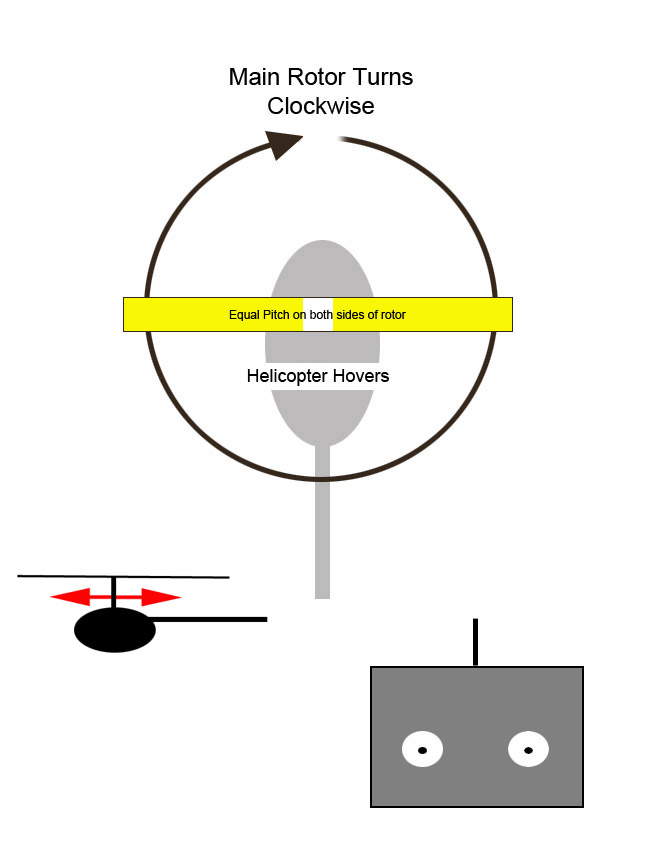
While hovering over the same spot the cyclic pitch of the main rotor blades is equal, meaning the both blades have the same pitch angle relative to the airflow. On a CP helicopter the pilot will control altitude in hover by adjusting the collective with the linked throttle control responding to change in load automatically. On a FP helicopter the throttle power directly controls altitude.
If you have flown airplanes with aileron controls or understand how they bank the wing of an airplane you will expect that the rotor will tilt in the direction of lesser lift on the rotor, but it doesn't. So its time for another lesson on the counter-intuitive physics of rotary flight. The difference between an airplane wing and a helicopter rotor is that the rotor is spinning. Spinning bodies are subject to a force called "Gyroscopic Precession”.
Gyroscopic Precession
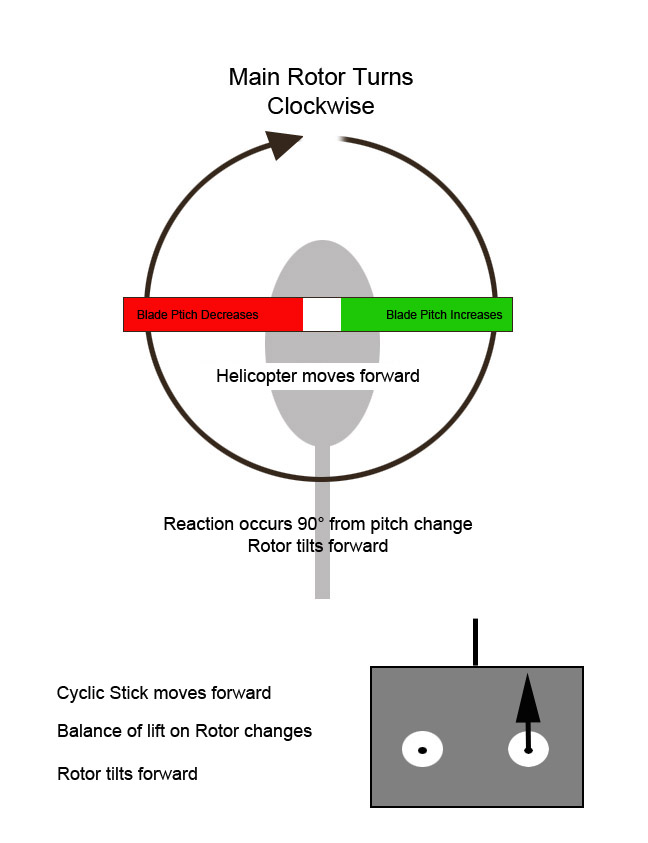
If you took a physics class at any point in your formal education you may have performed a the classic demonstration of gyroscopic precession in which you sit on a stool or chair that can spin around, hold a spinning bicycle wheel in outstretched arms, then try to move the wheel. The wheel resists turning and instead you spin around on the stool. That cause and effect is called "gyroscopic precession”. When force is applied to a spinning rotor like a bike wheel or helicopter flybar and rotor, the change direction occurs 90° at a right-angle to the input.
What that means in terms of moving a helicopter rotor is that to move the helicopter forward the controls much tilt the rotor forward but to do that they most vary the balance of the two blades - the cyclic feather pitch - when the rotor is passing to the sides of the helicopter, not when it is over the tail and nose.
The illustration above shows where the cyclic pitch is changed during rotation on Blade model helicopter or any other where the main rotor rotates clockwise (CW). The rotors on most real helicopters built in the U.S. rotate counter clockwise in the cyclic pitch change would be opposite the illustration above.
Now it starts to get really complicated...
The fact lift changes on the opposite sides of the rotor 90° from the direction the rotor actually tilts partially explains why a helicopter deviates in forward flight in ways beginners don't expect or understand. Understanding is further complicated by the rather unique design of the Blade models which have a 45° flybar system instead of the conventional 90° flybar design of larger models and real helicopters.
In the sections below I'll first discuss the different inter-related concepts and variables which affect rotary flight, then explain how a Blade model flies forward and self-corrects back to hover and how flying a CP model is different. Like I said earlier its a puzzle with a lot of different pieces.
Speed and Lift
Increasing air speed over a wing increases lift the amount of lift it generates. That's why jumbo jets have such small wings relative to their overall size and need to extend flap and increase wing area when moving slowly.
Transitional Lift
Transitional is the change in lift which occurs as a helicopter moves forward from hover and increases speed. Transitional lift will also occur if a gust of wind hits a hovering helicopter. As the forward speed of a helicopter increases the transitional lift will cause it gain altitude and as it slows it will lose altitude due to the reduction of transitional lift. This is often not noticed on Blade model because of the flybar induced pendulum effect when speed is changed abruptly.
Tip vs Root Speed
The entire leading edge of an airplane wing travels through the air at the same speed, but on a rotor "wing"of a helicopter the speed at the tips relative to the air is much faster than the root of the rotor. This causes the rotor to generate more lift at the tips than root. If you examine the shape of the rotors of the mSR and 120SR you will notice that they are wider near the rotor head. That has the same cause and effect as extending the flaps on an airplane wing to increase surface area and lift during the slower parts of flight.
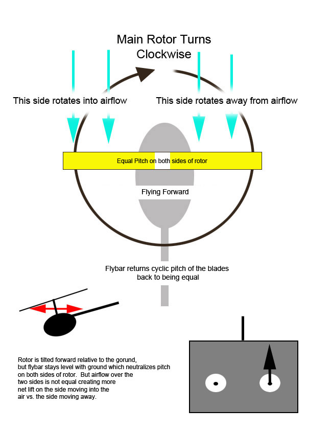
Dissymmetry of Lift
The most obvious difference between the wing of an airplane and rotor of the helicopter is that the rotor is turning. What is less obvious is how the direction of rotor and helicopter affect the symmetry of the lift. Since the rotor of the Blade models turn clockwise, when moving forward the left half of the rotor advances into the wind and generates more lift than the right side which is retreating from the wind. As the forward speed of the helicopter increases so does the dissymmetry of lift.
One of the reasons a coaxial model helicopter is more stable than a single rotor motors is that the dissymmetry of the two counter-rotating rotors balance each other out. But the stability comes at the cost of speed because the two rotors create twice as much drag. The Sikorsky X-2, the current holder of the helicopter speed record, is a coaxial with a airplane style pusher propeller in the tail.
Leading / Lagging and Flapping
When cyclic input changes the pitch of the blades in opposite directions the tip of the one pitching up more rises and slows due to more drag (flaps up and lags) while at the same time the other side of the rotor falls and speeds-up due to less drag (flaps down and leads). This explains why helicopter rotor heads are allow the blades to swing freely. On models like Blade mSR and 120SR both the blade grips and the blades flex up and down and allow the tips to flap as pitch changes. Full size helicopters use a dual hinge system.
Centrifugal Force
When the main rotor of a helicopter spins-up centrifugal force pulls the hinged blades out straight form the hubs.
Dishing
The centrifugal force will pull the blades out flat and level with the ground, but once the helicopter is in the air the mass of the body and the greater lift on the rotor tips will cause the rotor to form a shallow V shape referred to as "dishing”. Some degree of dishing is incorporated into the design of the rotor blades and hinging system because it creates stability, but too much dishing will cause a loss in overall lift.
Static Balance
If there is a difference in weight between the two rotor blades of a helicopter the rotor or fly bar paddles they are said to be out of static balance, which will cause oscillation and vibration when they spin. A helicopter is also designed with an overall static balance point called the center of gravity or COG, usually along the main shaft. On a real helicopter the COG will shift depending on fuel, occupant number, weight and location and cargo. On models modifications such as the use of larger heavier batteries or parts can shift the COG requiring adjustment of hover trim.
Dynamic Balance
Even if the two blades or fly bar paddles are equal in weight they may still vibrate and be out of balance if other factors such as unequal flexing make their lift unequal. The design of the rotor head and fly bar hub allow for a degree of free movement to allow the spinning parts to find their own equilibrium and dynamic balance. Without it any minor difference in static balance would cause oscillation and vibration which would shake the helicopter and make it uncontrollable.
Newton's Third Law of Motion
Single rotor helicopters have booms and tail rotors because without one the body of the helicopter would spin in a direction opposite the rotor according to Newton's Law of equal and opposite reaction. On Blade models the main rotor turns CW and the tail rotor thrust also pushes the tail CW to counter act the torque of the main motor. Coaxial helicopters solve the problem of torque by using counter-rotating main rotors. On a real helicopter the tail orientation is controlled with pedals similar to those for a rudder on an airplane but on a real helicopter they are referred to as "anti-torque"pedals because instead of moving a vane on the tail they counter act the rotational torque of the motor driving the main rotor.
The pedals on a real helicopter or servo on larger CP model change the pitch and thrust of the tail rotor which is linked mechanically by a shaft and gears or belt-drive to the main rotor shaft and single drive motor. Small model helicopters like the mSR and 120SR use a separate electric motor to drive the tail rotor which is mechanically simpler, but less responsive than the CP variable pitch tail.
Real helicopters pilots need to see where they are going mostly use the rudder pedals to keep the nose oriented in the direction of flight. On a model helicopter the direction of the nose is pointing is less important than how the main rotor is tilted and the direction is pulling it. The rotor tilt is controlled with the "cyclic"stick.
Clean and Dirty Air
Rotors generate thrust by slicing through the air and making it move faster over the bottom than on the top. That process works best when the rotor moves through undisturbed or "clean"air.
An airplane wing by virtue of moving forward is always in "clean"air. But a helicopter in hover near the ground sits in the vortex turbulence created by spinning rotor, referred to as "dirty"air which can affect lift and stability. If you have an opportunity to observe real helicopters taking off and landing you will observe they do it very much like airplanes, flying forward and up immediately after take-off and moving forward and down at a shallow angle (glide path) when landing. That is because the most unstable scenario for a helicopter is a vertical descent straight down from hover where it flies into the "dirty air"downwash of its own rotor.
It's a Minor Miracle a Helicopter Can Can Fly
All the variables discussed above, individually and various combinations, affect the flight characteristic of a helicopter. Early attempts to design helicopters with rigid propeller style rotors vibrated and shook to pieces. Spanish engineer Juan de la Cierva in his pioneer work on the autogyro in the 1920s is credited with solving many of the puzzles of rotary flight dynamics, such as the use of hinges to allow the rotors to lead and lag for conservation of momentum, flap up/down to compensate for dissymmetry of lift, and dish to add stability. Autogyros have a non-powered rotor which generates lift when the aircraft is pushed forward with an airplane style propeller mounted under the rotor. Because there is no motor and there is no motor torque and no need for a tail rotor on an autogyro to counter-act it.
Igor Sikorsky, a pioneer in fixed-wing aircraft designed solved the problem of powered rotor torque in the late 1930s by inventing the boom mounted tail rotor, used on helicopter with a three-blade main rotor the VS-300. His three-blade model R-4, first produced in 1942 was the first mass-produced helicopter.
Authur H. Young, working for Bell Aviation in the 1930s solved the problem of stabilizing a two-blade helicopter rotor by adding a weighed bar 90° from the rotor it stabilize it. The Bell-47 based on Young's stabilizer bar rotor concept was the first helicopter certified for civilian use in 1946.
In 1944 Stanley Hiller Jr., then only 17, designed a coaxial helicopter and two-years later at 19 flew the XH-44, the first coaxial design successfully flown in the U.S. Hiller later invented the self-stabilizing Hiller-Matic fly bar paddle system which was incorporated into the Hiller H-23 helicopter used in the Korean War and featured in the movie and TV series MASH.
Successful RC helicopters didn't appear until the mid-1970s because it was difficult to simply scaled down any of the commercial models of Sikorsky, Bell or Hiller. Dieter Schluter, by combining the self-correcting paddle flybar concept of Hiller with the gyroscopic stabilization bar of the Young/Bell created the hybrid Bell-Hiller rotor head design which made RC model helicopters stable enough to fly.
What exactly is a Flybar?
Arthur Young's (Bell) design used a thin bar with weights on the ends 90° from the rotor blade as a dampener. The spinning weigh creates a gyroscopic effect that counteracts and dampens the 90° precession reaction of the main rotor. The movement of the rotor blades in a Bell design is done with direct links from swash-plate to rotor requiring powerful hydraulic servos in the full-scale designs. There are no winglet airfoil on a Bell design so its more accurately described as a stabilizer, not a "fly" bar.
Hiller's concept, while looking similar to that of Young operated entirely differently. Instead of heavy duty servos moving the main rotor blades Hiller attached the main rotor control links to a light weight bar with small air foil "paddles"on the end; a flying bar or "flybar"which like Young's design was 90° from the main rotor. When the pilot moves the cyclic it changes to the angle of the lightweight flybar, which the flies onto a new plane. The linkages between flybar and main rotor change the pitch of the main rotor blades tilting it.
One advantage of the Hiller design versus Young/Bell are that very little force is needed to move the main rotors. The flybar acts like power steering to amplify the control inputs using aerodynamics rather than brute force from servos. The second trait of the Hiller system is that is self stabilizing. That is a big advantage when the helicopter is hovering. A photograph of Hiller testing the a H-23 prototype shows him on the ground below a helicopter with sandbags in the pilot seat. But that same self-stabilizing trait is the underlying cause of the "pendulum"effect when trying to stop a moving helicopter.
The Bell-Hiller Hybrid on RC models
Larger collective pitch RC model helicopters use a combination of the Bell and Hiller designs. Three servos spaced 120° from each other around the swash plate are used to move the swash plate both collectively (all servos moving together to move the swash up/down) and in a coordinated manner to tilt the swash plate and change the cyclic feathering pitch of the rotor. The transmitter controlling the model translates stick movements into the necessary swash plate movement using a process called CCPM - Collective Cyclic Pitch Mixing. Controls on the transmitter allow tuning the mix.
The airfoils on the flybar paddles (the Hiller part) amplify the servo input making it possible to use small servos to control the main rotor. The stabilizing effect (the Bell part) is accomplished by increasing mass of the paddles to create a gyroscopic stabilizing effect opposite the precession of the main rotor. Larger RC models have movable weights on the flybar arms which allow the pilot to "tune"the performance of the flybar. Moving the weights (and spinning mass) out towards the paddles dampens the movement of the flybar and makes the model slower to react and more stable. Moving the weights in towards the shaft, or removing them entirely make the model more responsive to control input, but less stable.
The 45° Flybar Design
Both the Bell and Hiller concepts use a flybar which is 90° from the main rotor to counter balance and dampen the effects of gyroscopic precession and other factors. My research into 45° flybar design indicates it first appeared on fixed pitch micro helicopters produced by Hirobo and was also adopted by Blade in the design of the mSR and 120SR use a fly bar which is 45° degrees from the main rotor. What I find interesting is a lack of information about how, exactly, the 45° flybar design works on a cause and effect level, so what follows is my intuitive guess based on observation. In terms of design the most significant difference between CP and FP helicopters is the use of only two servos spaced 90° apart to control the forward and sideways tilting of the main rotor. The third attachment point for the swash plate is a pin which floats freely in a vertical guide. The two control arms are at 45° angle relative to the centerline of the model.
Spinning on the ground before liftoff the swashplate, flybar, and main rotor are parallel to each other and the ground. The links from swash-to-flybar keep it level, and that in turn keeps the cyclic feathering pitch neutral allowing the helicopter to rise into a hover when sufficient power is applied..
To observe how the control system operates I manually moved the elevator servo link of my mSR to where it would be if I was holding the right cyclic stick fully forward. Then keeping the flybar level with the ground - as it would be when spinning in flight - I observed what happens to its orientation as it rotates over the swash.
I observe that when the flybar passes 90° from the elevator control arm the tilt of the arm changes the tilt of the flybar and its airfoils and the links from flybar-to-main rotor change the cyclic feathering pitch. When this occurs the main rotor, which is 45° from the fly bar is passing over the sides of the model - increasing pitch on the right side and decreasing it on the left, exactly where the pitch change must occur to produce the precessional tilt of the rotor forward 90° later.
The flybar on the mSR and 120SR are more Hiller than Bell because there is no direct control linkage from swash-to-rotor, what defined a "Bell"design. The other feature of the Bell rotor is the use of a stabilizer bar at right angles to the rotor. To the extent there is a Bell influence in the design of the Blade models it is that the paddle blades have greater mass, creating more inherent gyroscopic stability than Hiller's original concept which used lighter airfoils to literally fly the flybar into a new plane. That flying dynamic is what amplifies the input and allows the use of less powerful servos than would be required in the Bell system in which the servos move the main rotor directly.
Anyone who has flown an mSR or 120SR knows it is necessary to keep the cyclic pressed forward to maintain the tilt of the rotor and forward flight and how it returns to hover (after a pendulum swing if moving fast) when cyclic stick is released and returns to center. What is less apparent is the cause and effect which makes this happen.
Real helicopters and CP models operate differently. After pushing the cyclic forward to tilt the rotor forward and initiate forward movement the pilot must then immediately return the cyclic to neutral, otherwise the continued application of cyclic would flip the helicopter tail over nose. Pilots of real helicopters try to avoid that situation but model fliers use that cause and effect flip, roll (with aileron input) and invert the helicopter for stunt flying. But once inverted the CP model must quickly reverse the collective pitch of the rotor to prevent it from flying straight down into the ground. FP models can be modified to flip but cannot reverse collective pitch which is why they cannot be flown inverted.
In the Hiller design the cyclic pitch of the rotors in controlled entirely by the attitude of the flybar. The air foil shape of the paddles will act to fly it onto a different plane when it's equilibrium is changed by the swash plate tilting, but gyroscopic effect of the mass of the paddles will move it back to a plane level with the horizon. What happens dynamically over time is that the control input tilts the swash, the tilted swash changes the plane of rotation of the flybar, that changes the cyclic pitch of the rotor, the rotor tilts, but then the momentum of the flybar keeps it level with the horizon, which again changes cyclic pitch of the main rotor blades back to neutral, maintaining the angle of tilt of the rotor at a constant angle.
The self-correcting characteristic of the Hiller flybar is counter-balanced by the tilting of the swash plate when the stick is held forward to tilt the swash. When the stick is centered the flybar reacts in the same manner, but in the opposite direction. It's rotational momentum keeps it level with the horizon while the momentum of the body of the helicopter continues to move forward. That difference in angle between the body of the helicopter (and swash attached to it) causes the flybar to change the pitch of the rotor blades, tilting the rotor back and arresting forward momentum and pulling the body nose-up relative to the horizon. Gravity then pulls the body back down triggering another cycle of flybar induced cyclic pitch change on the rotor; the pendulum effect.
The Origins of the 45° Flybar
Curious about the origins of the 45° I searched with Google and found no clear explanation. I then searched the US Patent Database for "45° flybar"and came up empty. Then by broadening the search and looking in the pending application database I found what appears to be the first patent application for a rotor design with an "flybar at an acute angle”, i.e. less than 90°.
U.S. Patent Application 20100196161 filed in December 2009 by Hirobo, the makers of Quark model helicopters contains the first reference I was able to find to a flybar with an angle other than 90°. The application does not mention 45° specifically but explains how reducing the phasing angle between main rotor and flybar results in more stability for small lightweight models which have light weight flexible rotor blades. Here are the pertinent sections of the application...
[0019]That is, as in the outdoor R/C helicopter, when the main rotor blades are made of wood or FRP and have high rigidity and heavy weight, the gyro pre-session appears after being delayed by 90 degrees with respect to an input. Using these characteristic, a steering operation is input at an advanced place by 90 degrees with respect to a moving direction of the main rotor, that is, the swash plate is inclined at an advanced position by 90 degrees, and the pitch angle of the main rotor is changed.
[0020]Meanwhile, it is revealed that the gyro pre-session appears in a range lower than 90 degrees with respect to the input, as a result of confirmations of a position where the gyro pre-session appears by trial and error, when the light-weighted main rotor blades made of a plastic material such as expanded polystyrene is mounted to the R/C helicopter configured to have a small size to be used indoors.
[0021]On the basis of the knowledge, in the rotor head of the R/C helicopter of the Bell-Hiller type that is configured to have the small size to be used indoors, the main rotor is adjusted such that the phase angle of the main rotor as the output with respect to the operation input becomes an acute angle lower than 90 degrees, that is, the main rotor is disposed around the mainmast such that the mounting position of the main rotor from the mainmast is advanced by the appropriate angle, and the main rotor and the stabilizer are configured to rotate with the phase difference of the acute angle.
[0022]It can be confirmed that operability is greatly improved that when the R/C helicopter comprising the rotor head is made to fly, the airframe does not shake and maintains the stable flying posture and even when the flying direction is changed, the flying posture is not collapsed, the behavior of the airframe is stabilized, and the smooth flying in a desired direction is enabled.
[0023]It is thought that in the R/C helicopter of the Bell-Hiller control type, due to a change of the rotation surface of the main rotor which is made by the cyclic pitch control and the stabilizer which seesaws above the mainmast as well as the position of the main rotor is advanced by an appropriate angle and the main rotor is disposed such that the phase difference with the stabilizer becomes the acute angle, a direction of the force applied to the airframe by the gyro pre-session in the rotation surface of the main rotor and a control direction of the airframe are matched with each other, and the arrangement of the main rotor is appropriate.
[0024]According to the present invention, in the rotor head of the R/C helicopter that is configured to have the small size and the light weight, the phase angle of the main rotor with respect to the operation input from the swash plate is adjusted in a range of the acute angle, not 90 degrees, and the phase angle of the rotation of the main rotor and the stabilizer is also set to the acute angle. As a result, the flying operation of the R/C helicopter can be stabilized and the operability can be greatly improved.
[0025]Accordingly, the problem according to the related art in that the control operation of the indoor helicopter is difficult can be resolved. Even when the setting place of the airframe or the transmitter is not precisely adjusted and the operator lacks his/her operation skills, the operator can enjoy the control of the R/C helicopter indoors without difficulty.
[0026]According to the experiments of the inventors of the present invention, it is confirmed that the range of the phase difference of the rotation of the main rotor and the stabilizer is different depending on the configuration of the R/C helicopter, such as the weight or the size of the main rotor blade and the total weight of the airframe. For this reason, the optimal phase difference (angle) to achieve the stable flying needs to be appropriately adjusted and set according to the configuration of the R/C helicopter. Even in any case, when the main rotor blade is light-weighted, the gyro pre-session appears after being delayed by the angle lower than 90 degrees with respect to the input. In order to stabilize the flying operation, the phase difference of the rotation of the main rotor and the stabilizer needs to be maintained at the acute angle.
In June of 2012 I was contacted by John Strachan who was involved in the hobby in the formative years in the 70's and had stumbled across this page. He made me aware that the Hirobo patent was derivative and based on the work and patent by of Alexander Van de Rostyne several years earlier. John graciously provided this link to Wikipedia and another to Van de Rostyne's 2006 patent for the acute angle flybar concept which makes the Blade models self-stabilizing:
Wikipedia entry about Van de Rostyne's Picoo model
According to John, who patented some of the gyro concepts used in the models, Van de Rostyne became friends with Dieter Schluter who he describes as the father of RC helicopter development and Petter Muren who was developing coaxial rotors models at the time. Van de Rostyne and Muren entered into a friendly competition to see who could create the smallest, lightest model.
Schluter, Van de Rostyne and Muren were known to everyone in the RC helicopter universe in the 1970s because that universe was very small. One of the things which happens when something that was so complicated is made so simple anyone the buy a model and have it pop into a hover literally out of the box is that we lose sight of whose shoulders we are standing on. So I tip my hat and raise a glass to these pioneers and people like John whose innovation made the models we use today possible and affordable.
Learning to Live with the 45° Flybar
Life is full of compromises. The clever 45° flybar design is what makes the models self-stabilizing and easy to fly. But the same cause and effect which creates the stability also causes the swinging pendulum effect when direction is changed rapidly with the cyclic stick and the Toilet Bowl Effect (TBE) where the model wanders in a clockwise circle like the water in a flushing toilet when slop in the control links or a out-of-phase bend flybar causes cyclic pitch to vary, similar in cause and effect to the pendulum effect but occurring in two directions and influenced by precessional forces.
The pendulum effect can be avoided by not making sudden changes in direction, but what fun is that? So as they say if you can't beat 'em, join in. The pendulum effect can be used to advantage to turn 180° by flipping the tail around as the nose reaches the apex of its first upward swing, the jamming the cyclic forward, goosing the throttle and zooming off in the opposite direction. That maneuver is the simplest way to avoid a crash. The root cause of TBE is the cyclic pitch of the rotor changing by itself without any pilot input. A drift off in one direction will result in the flybar trying to move it back in the other direction (the pendulum effect). But if the flybar arms or paddles are bent it will not react exactly opposite (i.e. in correct phase with the precession of the rotor) resulting in the circular motion. Simply put the best way to avoid TBE is to avoid crashes which bend a crack the parts in ways that are impossible to detect.
The main goals in this long missive was to make a beginner to the hobby of flying these big boy toys is that there is much more to their design which meets the eye. To the uneducated eye the Blade models and other it its price range appear to be made of plastic materials because that is cheaper. While that is no doubt a factor the materials selected they are also selected based on their ability to flex, move and perform the same functions as the flapping hinges on the rotors of full-scale helicopters to dampen vibration. The rotor blades flop sideways and flex up and down in the blade grips and the blade grips by design.
Getting yourself oriented when flying a model:
Flying a model helicopter gets disorienting because the pilot isn't sitting it reacting to the tilt of the helicopter relative to the horizon. Most tutorials for RC models dwell on learning separate reactions for flying "tail-in"vs. "nose-in”. I find it much simpler and less confusing to instead think in terms of:
1) flying straight
2) turning clockwise (CW - with the main rotor)
3) turning counter-clockwise (CCW - opposite the main rotor direction)
It is less confusing because regardless of where the nose is pointing you always move the rudder and cyclic sticks right to execute a banked CW turn and move both left to execute a banked CCW turn. A figure 8 flight will be either CW / CCW or CCW / CW and thinking in those terms makes it easier to instinctively move the sticks in the correct direction. There is also another good reason to think of flight plans in terms of CW and CCW turns which relates to what I'll discuss in the next section: helicopters react differently when turning with or against the rotor, for reasons which are not apparent by simple observation.
What All That Stuff Means in Practical Terms
Fixed pitch models with 45° flybars are unique in their ability to hover hands off. It's more or less a no-brainer once the model is correctly trimmed. But as mentioned above that stability comes at the cost of the model swinging like a pendulum when direction is changed rapidly and TBE if the flybar gets out of its 45° phasing for any reason.
Forward flight is in one sense just a hover with the rotor tilted because cyclic pitch the blades of the rotor in forward flight is the same as at hover: equal on both sides. But forward flight, or straight flight in any changes the rate of airflow over the two blades differently, with more lift created on the side moving into the direction of flight and less on the side retreating. That difference in lift, plus the fact the thrust of the tail rotor is pushing the body CW to counter the main rotor torque is what will cause the CW rotating Blade models to bank and drift in the same CW direction as the rotor. Flying straight requires a corrective adjustment of left cyclic. So in effect to flying straight requires applying the same input as making a CCW turn: moving the cyclic left. The same dynamics will be in play when you are flying fast in a straight line (by inputting left CCW cyclic) then decide to turn CW or CCW. Because the CW rotor has a natural physical tendency to bank CW on its own the helicopter will respond very quickly to the right cyclic input used to initiate a banked CW curve and the model. As the rotor initially banks sideways it will tend to shall requiring front/back adjustment of cyclic (elevator) to maintain the desired turn radius and more throttle counteract a loss in overall lift resulting from the rotor tilting more than it had been in forward flight. When trying to duplicate the same banked turn in the opposite CCW direction you will find the model will not seem as responsive and need more cyclic stick input to bank it at a similar angle and more coordinated corrective action because the turn is being made opposite the rotor direction and its natural inclination in the other direction. So in practical terms as a pilot of a Blade FP model you need to develop three slightly different sets of reflexes, one set for keeping the models flying straight and level, a second for making turns in the CW direction, and a third when needing to turn the model CCW. The quickest way to develop these reflexes is by practicing straight and level flight at various speeds, transitioning from forward flight to a CW banked curve, transitioning from forward flight to a CCW banked curve, and then finally transitioning from a CW banked turn to a CCW banked curve to create a figure-eight. Once you begin to envision flight as interconnected straight, CW and CCW legs and develop the instincts to control each of them instinctively the flight of the model will become an extension of your conscious thought to the point you don't even think about your thumbs or the transmitter. Psychologists call that skill level "unconscious competence": the point where you react instinctively based on reflexive muscle memory.That's when flying these things really gets fun, and like flying a real one you'll find crashes rarely occur.
RC Helicopters
Flying Up The Learning Curve
This tutorial is copyrighted by © Charles E. Gardner.
It may be reproduced for personal use, and referenced by link, but please to not copy and post it to your site.
You can contact me at: Chuck Gardner
For other tutorials see the Tutorial Table of Contents